Quick Nav
- The Monsoon Topography Challenge
- Topographical Analysis and Flow Mapping
- Step 1: Designing Discreet Catchment Systems
- Step 2: Subsurface Routing and Velocity Control
- Step 3: Ecological Retention and Harvesting
- A Complete Topographical Water Strategy
The Monsoon Topography Challenge
How do you integrate high-volume monsoon runoff into a sloped luxury site without compromising the architectural vision or causing severe soil erosion?
That question sits beneath every serious hillside residence in a monsoon climate. Rain does not arrive as a polite environmental input. It arrives as force, weight, sediment, leaf matter, roof discharge, surface sheet flow, and subsurface pressure, often within a single afternoon.
On sites where rainfall can reach, according to common estimates, 250mm to 400mm over a 24-hour period, and where gradients frequently exceed in the vicinity of 20 degrees, runoff becomes a design material. Treating it as a nuisance usually produces crude defenses: exposed drains, concrete gutters, oversized scuppers, and retaining walls that look more like civil infrastructure than architecture.
The baseline approach I use begins with a different premise: do not repel the water first. Read it. Then slow it, divide it, store part of it, and release the rest without letting it cut the site apart.
The dual risk is plain. High-velocity runoff can undermine foundations, scour planting beds, overload retaining walls, and drive water into weak soil seams. At the same time, visible erosion degrades the intended landscape composition. A luxury hillside house can survive the storm structurally and still look wounded by the morning.
Design Principle: A monsoon site does not need a hidden drainage system as much as it needs a topographical water strategy: catchment, friction, lateral distribution, retention, and safe overflow working as one sequence.
Topographical Analysis and Flow Mapping
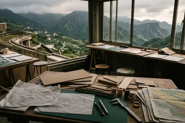
Before drawing roof edges or retaining walls, map the water that already belongs to the land.
The useful information rarely appears in a clean survey alone. Contours show slope, but they do not show which shallow depression wakes up during a hard rain, which footpath becomes a temporary channel, or where surface water decelerates because vegetation, stone, and soil texture already cooperate.
I start with field walking during active rainfall when possible. Mark every micro-valley, every natural retention pocket, and every high-velocity path where water carries leaf litter or fine soil. These marks should sit directly on the topographic drawing, not in a separate note file. If the project team records public drainage dependencies, name the relevant authority precisely; a specific permit office or municipal drainage agency is more useful than a vague note saying “city review.”
Engineers in comparable monsoon studies have placed retention zones by mapping micro-valleys during live rainfall first, then confirming the soil profile through deep-core tests. That order matters. If the design team tests soil before observing flow, it may understand absorption but miss movement.
Soil permeability testing should extend through the operative layer, typically at depths of circa 1.5 to 3 meters for this kind of hillside drainage planning. Where native percolation rates sit between 15 and 25 millimeters per hour, the soil can participate in the strategy, but it cannot be asked to swallow the entire storm. Clay lenses, compacted construction zones, and buried rock shelves change the answer quickly.

Field Mapping Sequence
- Walk the site during or immediately after heavy rain and mark visible channels, sediment fans, and ponding zones.
- Overlay those marks on the contour plan to distinguish true micro-valleys from incidental puddles.
- Locate proposed building edges outside the strongest flow paths where possible.
- Test soil permeability at several depths before assigning retention or infiltration duties to any zone.
- Draw overflow paths before drawing aesthetic landscape features.
Warning: Extreme events on the order of 500mm in a 48-hour window can bypass natural micro-valleys entirely, so engineered overflow redundancies must be part of the method rather than a late correction.
Step 1: Designing Discreet Catchment Systems
The roof should begin the drainage sequence without announcing it.
Standard residential gutters often fail under the sheer weight of monsoon debris and sudden water volume, leading to immediate foundation pooling. On refined architecture, they also tend to weaken the elevation. The answer is not to pretend the roof has no drainage burden. The answer is to make the roof geometry do visible architectural work while the catchment hardware stays disciplined and serviceable.
One early scheme relied on concealed internal PVC downspouts. During monsoon trials, debris loads and velocity made that logic too fragile; ruptures occurred where access was worst. The better move was to keep water paths open, legible, and still quiet in the composition.
Roof-to-Ground Transfer
Use integrated roof slopes to direct water toward architectural reveals, shadow joints, or stone-lined vertical planes. Rain chains can work when they are not decorative afterthoughts. Set them where falling water can enter a prepared ground condition immediately, not splash across paving and migrate toward the foundation.
At the foundation line, the primary catchment basin can read as luxury hardscape rather than utility. A gravel trench in the vicinity of 450mm wide by 600mm deep gives the falling water a receiving volume, a filtration bed, and a first point of deceleration. Stainless steel debris filtration mesh with 5mm to 8mm apertures, thereabouts, keeps leaves, twigs, and larger roof debris from entering the subsurface routing network.
- Align the trench with the roof drip logic, not with an arbitrary paving grid.
- Keep inspection access visible enough for maintenance but calm enough to disappear in the stone field.
- Use gravel color, edge stone, and paving joints to integrate the trench into the architectural language.
- Separate foundation waterproofing from drainage aesthetics; the trench is a catchment device, not a substitute for envelope detailing.
Maintenance Detail: Place the debris mesh where it can be lifted by hand after a storm. A concealed filter that requires tools will be ignored at exactly the moment it needs attention.
Step 2: Subsurface Routing and Velocity Control
Once runoff enters the ground-level trench, the project becomes a question of velocity.
Water moving downhill in a straight pipe behaves like a problem postponed. It may leave the building edge clean, then discharge aggressively at the lower garden, the toe of a retaining wall, or a neighbor's boundary. A sloped monsoon site needs friction, interruption, and lateral distribution.
The preferred system uses subsurface terraced channels connected to perforated pipe networks. Pipe diameters of 100mm to 150mm are typical within this strategy, depending on the catchment area and maintenance access. The pipes should not simply chase the steepest route. They should move across the slope, step down, cross again, and release water into drainage stone where the terrain can absorb and slow it.
Check Dams Below Grade
Check dams inside subsurface trenches act as deliberate pauses. Built from natural stone and gravel, they reduce the kinetic energy of water descending the slope and keep the drainage trench from becoming an underground chute. Modeling of downhill energy typically leads to staggered check dam intervals of 2.5 to 4 meters, thereabouts, on steeper residential terrain.

In standard test conditions, for gentler gradients of 10 to 15 degrees, a trench depth of 400mm to 500mm can pair with check dam spacing of 4 to 5.5 meters and drainage stone in the 20mm to 30mm range. For 16 to 25 degree gradients, trench depth often increases to 500mm to 650mm, while check dam spacing tightens to 2.5 to 4 meters. The depth of the subsurface terraced channels must increase proportionally as the soil's natural clay content rises, compensating for lower native percolation rates.
- Route laterally first: Make water cross the slope before it descends.
- Interrupt momentum: Use stone check dams as energy breaks, not decorative fill.
- Preserve access: Provide cleanout points where sediment is likely to settle.
- Protect walls: Never aim concentrated discharge at the back of a retaining wall without a relief path.
This is where the drainage section becomes architectural. Terraced retaining walls, garden plinths, and stepped paths can all conceal the routing logic while giving the water the long, slow journey it needs.
Step 3: Ecological Retention and Harvesting
The final stage stores, filters, and releases the slowed runoff.
At the base of the slope, deep-rooted bioswales perform better than ornamental depressions because they combine soil structure, plant resilience, and hydraulic capacity. Plant selection should come from adjacent undisturbed hillsides whenever possible. Species that remain stable in saturated soil and show strong root-shear behavior are more useful than imported plants chosen for a render.
A common bioswale soil mix for this application uses 60 parts sand, 20 parts compost, and 20 parts native topsoil. The sand keeps the profile open. Compost supports biological activity. Native topsoil helps the planted system remain connected to the site's existing ecology rather than behaving like an isolated planter.
This stage also offers a quiet opportunity for rainwater harvesting. A concealed cistern can receive a portion of the routed water after debris screening and before overflow. The goal is not to hoard every liter. The goal is to hold a useful reserve while protecting the landscape during peak flow.
Overflow as a Designed Event
Overflow pipes in the 150mm to 200mm range should connect the cistern and bioswale system to a lawful discharge point, such as municipal drains or a natural water body where permitted. The U.S. Environmental Protection Agency's material on green infrastructure and topographical hydrology is useful here because it frames runoff as a distributed landscape problem rather than a single pipe problem.
Warning: A bioswale without a defined overflow route is only a pond waiting for the wrong storm.
The most elegant systems make overflow visible only when it matters. A stone rill, a planted spill edge, or a dry creek bed can carry excess water without looking like emergency infrastructure for most of the year.
A Complete Topographical Water Strategy
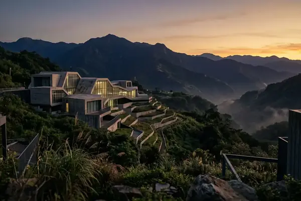
Use this worked case as a template: a villa placed on a 30-degree incline, with the main roof stepping with the slope and the primary living terrace cut into the hillside.
Worked Case: 30-Degree Incline Villa
- Set the roof geometry. Pitch the roof planes toward a continuous perimeter reveal so rainwater leaves the architecture along controlled edges rather than random eaves.
- Receive the roof water. At the base of those edges, install a continuous gravel trench measuring 450mm wide by 600mm deep, fitted with stainless steel debris filtration mesh with 5mm to 8mm apertures.
- Begin lateral routing. From the trench, connect to a perforated pipe network using 100mm to 150mm pipe, then run the pipe across the slope rather than directly downhill.
- Step through the retaining walls. Route the system in a zigzag pattern through three terraced retaining walls filled with 40mm to 60mm drainage stone, placing subsurface check dams at tight intervals where the descent is most aggressive.
- Store useful water. Direct a filtered branch into a 500-gallon concealed concrete cistern located below the lowest service terrace.
- Finish in the bioswale. Send cistern overflow into a deep-rooted bioswale built with 60 parts sand, 20 parts compost, and 20 parts native topsoil.
- Discharge the excess. Connect the final overflow through 150mm to 200mm routing pipes toward the approved municipal drain or natural receiving body.
On the drawing set, this case becomes three linked lines: the roof line catches, the subsurface line slows, and the planted line absorbs. Detail the gravel trench at the foundation, draw the zigzag pipe through the three stone-filled terraces, label the 500-gallon cistern below the service terrace, and carry the overflow pipe out of the bioswale. That is the copyable sequence: catch at the edge, cross the slope, interrupt the fall, store the reserve, then release the remainder through a planted base condition.