Quick Nav
- Defining Subterranean Ecosystem Preservation in High-Gradient Architecture
- The Topographical Vulnerabilities of Mountainous Terrain
- Analyzing Root Zone Mechanics and Soil Stability
- Executing the Micro-Pile Foundation Strategy for Luxury Villas
- A Foundation in Practice: The Undisturbed Forest Floor
Defining Subterranean Ecosystem Preservation in High-Gradient Architecture
Subterranean ecosystem preservation in architecture refers to the deliberate engineering practice of maintaining the structural integrity, hydrological pathways, and biological networks of soil and root systems during construction. Keep that definition close. Every later decision on a Next-Gene 20 slope is a test of whether the team still means it.
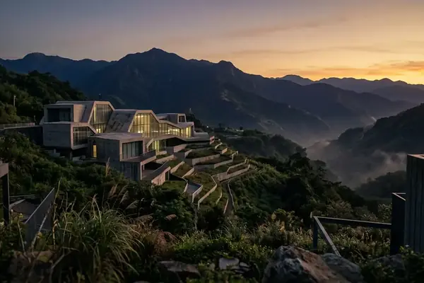
Luxury villas in this program meet the mountain on the mountain's terms. Twenty architects, twenty readings of ridge and ravine, one shared constraint: the building adapts to the terrain. The hillside keeps its profile.
Load Transfer With the Forest Still Intact
The micro-pile foundation strategy is the low-impact geotechnical solution that makes that constraint buildable. Small-diameter drilled and grouted piles transfer structural loads to competent bedrock. Mass excavation stays off the sheet. Where the engineering team calculated the minimum required load transfer area against the maximum allowable soil disturbance, small-diameter grouted columns supplied the bedrock anchorage while hydrological pathways remained continuous.
Pile diameters range from 150mm to 300mm. Drilling depths reach 12 to 18 meters, enough to engage rock that can carry a cantilevered residence through wind and wet-season surcharge. The columns occupy a modest fraction of the soil volume they pass through. Roots continue around them. Water continues past them.
A visitor can stand on the future terrace line and still smell the original duff.
Bedrock Without Clearing
Small-diameter grouted columns give each villa its anchorage while the forest floor keeps holding water, soil, and the hillside itself.
How much of a hillside does the drawing actually keep?
The Topographical Vulnerabilities of Mountainous Terrain
Taiwan's mountain belts offer few gentle pads. Gradients of 30 to 45 degrees are common on the Next-Gene 20 sites, and seasonal monsoon rainfall exceeds 2,500 millimeters annually. Disturbed soil on that pitch does not wait. It moves.
A conventional foundation crew looks at a slope and sees a cut. Traditional deep excavation and retaining walls need benches, haul roads, and a volume of earthmoving that severs the root mats holding the hill through decades of typhoons. Once those mats are gone, the soil matrix loses the tensile stitching that kept particles from sliding as a sheet.
What the First Cut Would Have Cost
Initial site proposals evaluated traditional stepped retaining walls to manage the slope. Geotechnical modeling demonstrated that the required earthmoving would critically reduce the soil's shear strength. Mass excavation left the program. A zero-disturbance approach took its place.
Step through a conventional cut and the losses stack in order. First the access track, which already nicks the drip line of trees later labeled retained. Then the bench excavation, which removes the 60 to 90 centimeters of tensile root that had been doing the work of a geogrid. Then the wall stem, which intercepts groundwater and forces it to find a new path, often along the back of the wall.
Monsoon Slope Risk
On 30-to-45-degree terrain, one wet season after mass excavation can undo years of natural anchorage. Keep the root mat, or plan for a hillside that will not stay.
Compare the two logics side by side. A retaining wall buys a level terrace by spending the living reinforcement already in the ground. A micro-pile cluster buys a level floor plate by reaching past that reinforcement into rock, leaving the living layer to keep working. The second logic costs more patience at the start. It spends far less hillside.
Analyzing Root Zone Mechanics and Soil Stability
Before anyone drills, the subterranean network gets mapped.
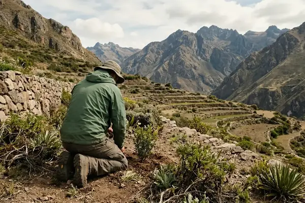
Arborists walked the canopy drip lines in the morning shade. Structural engineers laid those lines over subsurface radar scans the same week. Together they drew exclusion zones that later dictated the precise placement of every structural support. The sequence is simple on paper and slow in the understory: see the tree, infer the roots, refuse to put steel where the tree has already put its own.
Reading the Canopy to Place the Steel
Existing root systems function as natural tensile reinforcement for the soil, in much the same way rebar works inside a concrete beam. Fine roots bind particles. Larger laterals take tension when the slope wants to slump. That tensile root reinforcement extends 60 to 90 centimeters below the topsoil, which is the first horizon a backhoe would strip.
Critical root zones of mature trees set the no-go map for supports. Those radii were calculated at 1.2 to 1.5 meters per centimeter of trunk diameter. A trunk you can barely wrap your arms around claims a circle large enough to swallow a conventional footing. Villa loads have to find gaps in that circle, then drop through them like needles.
Compare a conventional spread footing with a micro-pile on this overlay. The footing wants a rectangle of stripped grade. A pile wants a point. That rectangle almost always collides with a critical root zone. The point can be walked until it does not.
Arborist surveys cross-referenced drip lines with radar returns, and the exclusion overlay became the construction set. Pile coordinates were acceptable only outside every critical root zone. Next-Gene 20 treated that tightness as the program.
Radar Then Probe
Non-invasive ground-penetrating radar mapping loses critical resolution in substrates containing high concentrations of dense rocky debris. Ground-penetrating radar attenuation in basaltic substrates leaves gaps in the picture, so crews rely on adaptive manual probing once the bit is in the hole.
That limit belongs in the method. The scans get the crew close. The cuttings tell whether the bit is still in mineral ground or about to clip a live lateral.
If the radar went quiet in basalt rubble, who is watching the spoil for green wood?
Executing the Micro-Pile Foundation Strategy for Luxury Villas
The Next-Gene 20 villas put the analysis to work in a sequence crews can count on one hand.
Five Moves From Overlay to Grout
Mark each pile from the exclusion overlay, never from a convenient grid that ignores a fern. Walk the kit in. Project managers selected modular, low-headroom drilling rigs that could be dismantled, transported by hand, and reassembled directly at the pile locations. Headroom clearances stayed under 2.5 meters, low enough to work under a mature canopy without topping a crown. No wide access road. No heavy earthmoving spread.
Then the hole. Small-diameter casings advance through the soil profile and into bedrock. Picture the micro-pile casing insertion bypassing mature fern critical root zones: a steel tube slipping past a living network that never sees daylight. High-strength steel reinforcement follows. Pressure grouting at 1.5 to 2.0 MPa closes the bond with the surrounding rock.
The load path is then honest. The villa sits on a cluster of slender columns. Each column is a grouted needle. The forest floor between the needles remains a forest floor.
- Stake pile points only where the exclusion overlay allows.
- Carry the modular rig by hand and reassemble it under the canopy.
- Drill the casing through soil and into competent bedrock at 12 to 18 meters.
- Set the high-strength steel reinforcement inside the casing.
- Pressure grout at 1.5 to 2.0 MPa until the column and the rock act as one.
Designers who want the numbers behind casing, grout, and bond length can consult the geotechnical guidelines for micropile design used in structural practice. The Next-Gene 20 application is residential and ecological. The mechanics of load transfer into rock remain the same discipline.
Cantilevered volumes come after the clusters are in. Those spans extend 4 to 6 meters outward from the micro-pile groups, which is how the architecture hovers over the drainage line. The final architectural orientation aligned the primary cantilevered volumes with the natural drainage corridors, so seasonal runoff could pass beneath the structure without encountering impermeable concrete barriers.
Walk the five moves again if a contractor proposes a shortcut. Skip any one of them and the hill gets cut.

A Foundation in Practice: The Undisturbed Forest Floor
Late afternoon under a completed Next-Gene 20 villa, first heavy rain of the season. The light beneath the soffit goes green.
Water sheets off the canopy and finds the same 30-to-45-degree gradient it has always used. It meets no basement wall. No grade beam interrupts it. During the peak of a typhoon-fed burst, stormwater runoff filters through the topsoil at 100 to 150 millimeters per hour, catching on the ancient fern roots that the casings were steered around.
A person standing in that narrow air between floor and leaf litter would hear rain. The cantilevers hold the rooms four to six meters out over the drainage corridor. The micro-piles take the weight into rock twelve to eighteen meters down. On the surface, a fern frond nods in the wet, still rooted where it germinated.
Citations
- Federal Highway Administration, geotechnical guidelines for micropile design