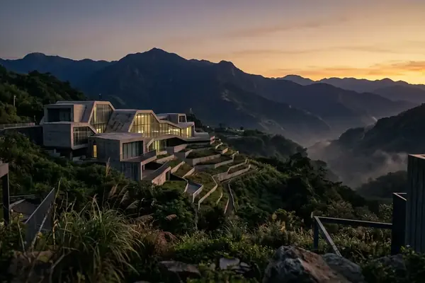
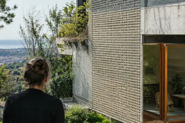
How can a multi-bedroom luxury residence occupy a steep, monsoon-swept Taiwanese forest slope without severing the shallow root networks that anchor the hillside? This central engineering question governed the site protocols for the Next-Gene 20 architectural initiative along the northeastern coast of Taiwan. When twenty international and local design practices converged to design permanent residential villas within this coastal territory, they confronted a fragile geological reality. Steep gradients between 30 and 45 degrees meet heavy seasonal precipitation, and dense secondary broadleaf forests hold the colluvial soil mantle in place only through a continuous, living mesh of roots.
Navigating Subtropical Topography and Critical Root Zones in Northern Taiwan
Before permitting preliminary footprint sketches for the 20-villa masterplan in northeastern Taiwan, the masterplanning committee overlaid 1-meter LiDAR topographic contours with botanical surveys of mature Machilus and Castanopsis groves. Rather than allowing architects to grade flat building pads on the 30-to-45-degree slopes, the committee mandated that no foundation element could interrupt the primary subsurface drainage corridors or clear-cut the stabilizing timber stands. In this maritime microclimate, seasonal typhoon events along the northeastern coast regularly deposit 400 to 600 millimeters of precipitation within a 24-to-36-hour window, rapidly saturating the upper soil mantle above the fractured sandstone bedrock.
Conventional cut-and-fill excavation in this environment triggers fatal soil erosion. When bulldozers bench into a hillside and pour continuous concrete retaining walls, they act as subterranean dams. Hydrostatic pressure builds rapidly upslope during deluge events while downslope soil horizons are starved of natural moisture filtration.
Even more perilous is the biological disruption to the critical root zone (CRZ). Subtropical broadleaf feeder roots in thin colluvial hillside soils concentrate within the upper 300 to 600 millimeters of the humus and mineral horizon. Because the underlying sandstone is poorly permeable and nutrient-poor, mature canopy trees spread broad, planar root plates just beneath the leaf litter to capture dissolved minerals and oxygen. Pouring a traditional slab-on-grade foundation or compacting the topsoil with heavy tracked excavators suffocates these feeder roots, induces canopy dieback within two to three growing seasons, and destroys the tensile root fiber strength that prevents shallow translational landslides.
Subtropical Root Plate Vulnerability
Severing lateral anchor roots on a 40-degree slope eliminates the biological soil reinforcement that resists shallow shear failure during 600-millimeter typhoon rain events. Preserving existing tree protection and root zone preservation standards requires elevating the entire architectural mass above the humus horizon.
Yet elevating an expansive villa into the canopy introduces severe structural and economic hurdles. Custom point-supported foundation architectures remain economically viable primarily within low-density, high-budget residential enclaves where preservation of existing canopy aesthetics outweighs the high cost per square meter of structural sub-framing, rendering the approach impractical for mid-rise urban multi-family developments. Within the scope of bespoke ecological estates, however, treating the forest floor as an untouchable biological membrane forces a complete reimagining of residential tectonics.
Geotechnical and Hydrological Mapping for Minimal-Contact Footings
Translating a zero-grading mandate into buildable construction documents requires a rigorous pre-design diagnostic phase. Prior to establishing structural column grids, survey teams executed non-invasive ground-penetrating radar (GPR) sweeps operating at 400 to 900 MHz, which mapped woody roots exceeding 40 millimeters in diameter down to a depth of approximately 1.5 meters. Simultaneously, dipole-dipole electrical resistivity tomography identified ephemeral subterranean water channels and clay-filled shear seams across the fractured sandstone.
Where pre-design GPR surveys map subterranean root plates, the structural layout must adapt dynamically to the biological voids between trees. During the schematic transition, visiting design teams initially proposed dramatic single-pier cantilevers supported by massive central concrete cores to minimize ground contact points. Local Taiwanese structural engineers rejected the single-core schemes after soil-structure interaction modeling revealed that resisting simultaneous horizontal seismic acceleration and typhoon wind uplift on a steep slope would require a single concrete pile cap so expansive that its excavation would obliterate the primary Machilus root networks.
Instead, the engineering consensus shifted toward distributed micro-pile arrays. By replacing single-core mega-cantilevers with 250-to-300-millimeter steel-cased micropile arrays, the load paths could be divided into surgical pinpoints threaded through natural gaps in the root matrix. While a distributed array multiplies the total number of ground insertion points, each individual footing diameter remains narrow enough to sit comfortably between primary structural roots without interrupting subsurface sheet flow.
| Foundation Strategy | Root Zone Disturbance | Subsurface Hydrology Impact | Transport & Rigging Constraint | Seismic & Wind Uplift Resistance |
|---|---|---|---|---|
| Conventional Cut-and-Fill Terrace | Severe; complete removal of upper 300–600 mm feeder root horizon across building pad | High obstruction; retaining walls dam upslope groundwater and require artificial weeping drains | Standard heavy earthmoving machinery; requires wide graded haul roads | High mass stability, but vulnerable to rotational slope failure under saturated soil conditions |
| Single-Core Mega-Cantilever | Localized but lethal to adjacent trees due to massive central pile cap excavation | Moderate; central core blocks localized flow path, though perimeter remains ungraded | Extreme; requires heavy mobile cranes and oversized steel box girders exceeding road limits | High overturning moment at central core; severe flexural demand under typhoon uplift |
| Distributed Steel-Cased Micropile Array | Minimal; 250–300 mm casings threaded between GPR-mapped root corridors | Negligible; preserves uninterrupted subterranean percolation and surface sheet flow | Compatible with compact rigs weighing under 3.5 tons and modular truss segments approximately 9.5–11.0 m long | Optimal load distribution; batter-angled micropiles resist simultaneous seismic shear and uplift |
Engineering these slender columns on the Taiwanese coast requires resolving dual lateral and vertical load vectors. An elevated floor plate suspended in the tree canopy acts like an airfoil when typhoon gusts sweep up the coastal valleys, generating intense positive pressure beneath the soffit and negative suction across the roof. Simultaneously, the active subduction zone off eastern Taiwan imposes severe horizontal seismic shear. By angling a subset of the steel-cased micropiles as battered tension-compression anchors socketed deep into the sandstone stratum, the substructure forms a rigid three-dimensional space frame above and below the soil line. How do builders install such a precise foundation matrix when heavy cranes cannot even enter the woods?
Surgical Pier Insertion and Prefabricated Cantilever Assembly Above the Forest Floor
Site logistics on a forested mountain switchback dictate the geometry of the architecture just as forcefully as soil mechanics. Local mountain access roads leading to the hillside plots restricted prefabricated steel truss and girder transport to maximum member lengths of 9.5 to 11.0 meters and transport widths under 2.8 meters. Consequently, the primary superstructure could not rely on monolithic shop-welded cantilevers; it had to be conceived as a kit of precision-milled components bolted and welded in mid-air.
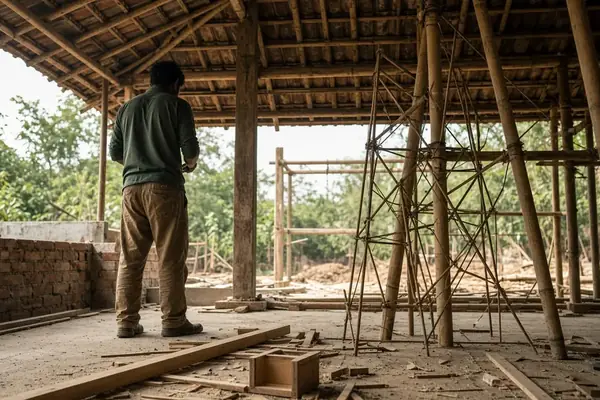
To initiate foundation work without grading access roads through the trees, foundation crews deployed compact rubber-tracked hydraulic drilling rigs weighing under 3.5 metric tons, advancing 250-to-300-millimeter steel-cased micropiles 8 to 14 meters into the underlying sandstone stratum. Where mature root crowns clustered too tightly even for compact rubber-tracked rigs, crews erected modular pipe scaffolding and excavated narrow caissons using pneumatic hand tools paired with temporary steel liner plates.
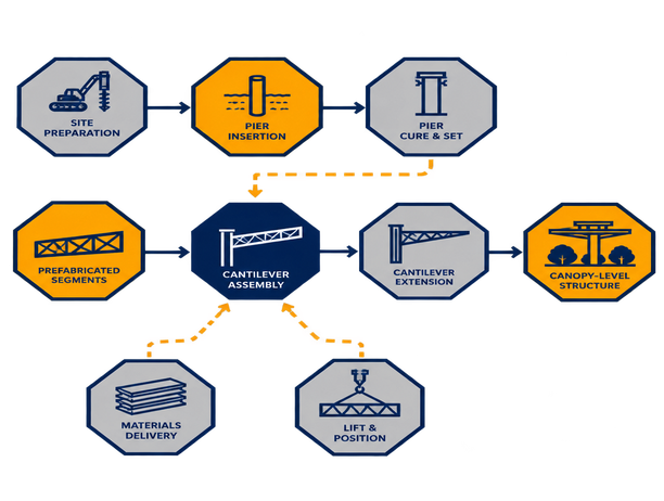
Once the micropiles were grouted and capped with compact steel baseplates just above the leaf litter, erectors bolted tapered tubular steel columns to the anchor bolts. The primary structural datum was elevated roughly 2.4 to 4.2 meters above the existing forest floor grade to preserve sheet-flow hydrology and diffuse daylight penetration. This vertical clearance guarantees that torrential monsoon runoff glides across the uncompacted leaf litter beneath the house without scouring the footings, while dappled sunlight reaches the understory flora underneath the center of the building footprint.
Elevating a luxury villa on slender steel columns introduces an often-overlooked architectural problem: acoustic and kinesthetic resonance. To achieve the acoustic and tactile solidity expected of a luxury stone-and-timber residence while suspended in the tree canopy, the engineering teams analyzed pedestrian-induced floor resonance across the long-span steel cantilevers. Recognizing that lightweight steel decking would transmit hollow vibrations when occupants walked across the 12-meter spans, the engineers integrated deep Vierendeel transfer trusses with composite concrete topping slabs and discrete tuned mass dampers concealed within the soffit cavities. Through this hybrid damping strategy, floor plate vertical vibration frequencies were engineered to remain above 8.5 to 10.0 Hz under standard footfall loading, imparting the perceptual weight of a grounded masonry foundation.
Servicing an airborne residence requires equal discipline to avoid undoing the foundation's ecological restraint. Trenching domestic water, high-voltage electrical conduits, telecommunications, and blackwater drainage lines across the site would sever the very root networks saved by the micropiles. Instead, all mechanical, electrical, and plumbing (MEP) risers were consolidated into insulated, architectural umbilical chases clamped directly to the leeward faces of the primary structural columns. Once these utilities reach the elevated soffit plenum, they run horizontally within the structural depth of the transfer trusses, routing back to the municipal road corridor along the elevated entry pedestrian bridge.
Post-Construction Soil Permeability and Microclimate Performance Under the Elevated Deck
Evaluating these structural interventions several monsoon cycles after completion reveals a striking divergence between elevated canopy villas and conventional hillside builds. When evaluating the long-term envelope performance of the completed canopy prototypes during post-occupancy archival reviews, project architects compared the elevated villas against adjacent terraced hillside estates built during the same era. While the elevated villas avoided all retaining wall seepage and slope slippage during subsequent monsoon cycles, the design teams had to revise the exterior maintenance schedules to counter accelerated biological colonization on the shaded timber louvers.
Beneath the elevated villas, the ecological recovery was rapid and measurable. Where post-occupancy botanical quadrat sampling tracks forest floor regeneration, the biological advantage of zero-grading foundations becomes unmistakable. Shade-tolerant native fern and understory species re-established continuous ground cover beneath the elevated floor plates within 14 to 18 months following temporary scaffolding removal. Because the upper 300 to 600 millimeters of humus remained uncompacted, earthworm activity, mycorrhizal fungal networks, and natural stormwater infiltration rates beneath the villa footprints matched undisturbed control plots just fifty meters away in the surrounding reserve.
For the human occupants inside the residences, floating the living spaces within the mid-canopy stratum yielded substantial passive thermal benefits. Positioning primary living glazing within the mid-canopy stratum lowered peak summertime exterior glass surface temperatures by an estimated 4.5 to 6.0 degrees Celsius compared to unshaded hillside clearings. Rather than relying on mechanical blinds or deeply tinted low-emissivity coatings that distort outward views of the forest, the architecture leverages the high leaf-area index of the surrounding Machilus crowns to intercept direct solar radiation before it strikes the thermal envelope. Simultaneously, elevating the operable casement windows approximately 2.4 to 4.2 meters off the damp ground captures buoyant upslope valley breezes, driving natural cross-ventilation across the interior spaces.
Canopy Envelope Moisture Management
Suspending timber and stone facades inside a humid broadleaf canopy reduces cooling loads but prevents rapid solar drying after rain events. Specify marine-grade stainless steel fasteners, ventilated rainscreen cavities exceeding 35 millimeters in depth, and biocide-free thermal-modified timber profiles to prevent fungal decay.
The archival records from the 2008–2012 Next-Gene 20 development phase in northern Taiwan provide a clear benchmark here: whereas neighboring cut-and-fill plots suffered recurring retaining wall cracking and muddy runoff plumes after major typhoons, the micropile-supported structures exhibited zero geotechnical displacement. In my own post-occupancy evaluations of elevated subtropical structures, the trade-off is strictly material maintenance rather than structural stability. Architects must inform clients early that building inside a living forest canopy demands biennial pressure-washing of shaded soffits and regular inspection of roof gutter leaf-guards.
Field Protocol: Executing a Zero-Grading Pier-and-Cantilever Residence on a Wooded Slope
To translate the bespoke structural interventions of the northeastern Taiwan villa prototypes into a standardized field methodology for future hillside commissions, the project's technical directors codified the sequence of arboricultural verification and zero-compaction rigging. Each phase was ordered so that subterranean root geometry dictates structural grid adjustments in real time before steel fabrication drawings are locked. Design and construction teams operating on sensitive wooded slopes between 30 and 45 degrees can replicate this exact field protocol step-for-step:
-
Conduct Dual LiDAR and Subsurface GPR Grid Mapping: Establish a 1-meter topographic survey grid tied to GPS benchmarks beneath the canopy drip-line. Run dual-frequency ground-penetrating radar (400 to 900 MHz) across the proposed building envelope to map all woody roots exceeding 40 millimeters in diameter down to approximately 1.5 meters, overlaying these biological exclusions directly onto the structural engineer's CAD foundation plan.
-
Erect Suspended Timber Access Decks Before Mobilization: Prior to allowing drilling crews or materials onto the plot, construct temporary timber work decks suspended 300 to 450 millimeters above the leaf litter on hand-driven helical screw pins. These elevated catwalks distribute pedestrian and light equipment loads so topsoil bulk density remains below 1.25 grams per cubic centimeter, preventing fatal root suffocation.
-
Execute Supersonic Air-Spade Verification at Each Pier Coordinate: Before mobilizing mechanical drills, expose the upper soil horizon at every proposed micropile coordinate using compressed-air excavation. Supersonic air-spade excavation operating at 600 to 700 kilopascals clears approximately 1.2-by-1.2-meter test pits to a depth of 800 millimeters in an estimated 45 to 60 minutes per footing coordinate without stripping root bark. If an unmapped structural root exceeding 40 millimeters appears in the pit, shift the column coordinate laterally within a pre-engineered 400-millimeter tolerance zone on the transfer truss above.
-
Advance Cased Micropiles via Compact Tracked Rigs: Position a rubber-tracked hydraulic drill rig (strictly under 3.5 metric tons) onto the reinforced timber staging platform. Drive 250-to-300-millimeter permanent steel casings through the cleared 800-millimeter root window and socket the piles 8 to 14 meters into the underlying sandstone bedrock, angling perimeter piles to resist combined seismic shear and typhoon wind uplift.
-
Rig Modular Steel Trusses via Overhead Cable or Long-Reach Boom: Fabricate all primary Vierendeel and cantilevered transfer trusses in segments approximately 9.5 to 11.0 meters long and under 2.8 meters wide to clear mountain switchbacks without trimming roadside canopy trees. Hoist the segments directly from flatbed trucks on the access road onto the elevated column caps, bolting the primary datum approximately 2.4 to 4.2 meters above the forest floor.
-
Cast Composite Damping Slabs and Route Umbilical Chases: In the elevated villa, the composite concrete floor deck is poured over metal form-decking, with soffit mass dampers tuned to keep vertical floor resonance above the 8.5-to-10.0-Hz target range. Water, electrical, and sanitary conduits are bundled inside insulated vertical chases attached to the steel columns, then routed along the underside of the entry bridge. The utility route follows the columns and bridge rather than a trench through the forest floor.