Quick Nav
- Twenty Villas on One Hillside With No Shared Glances
- Cutting Sections Every Five Meters: The 12-Degree Roof Cap
- Berms, Pandanus and Rotated Glass Along the Service Corridors
- Seclusion Rules Worth Carrying to the Next Estate
Twenty Villas on One Hillside With No Shared Glances
One wrong sightline is enough. If a single upper terrace looks into a lower courtyard pool, an architectural icon becomes a suburban neighbour, and the premise of the whole coastal estate weakens with it. Ultra-luxury seclusion has very little tolerance for error.
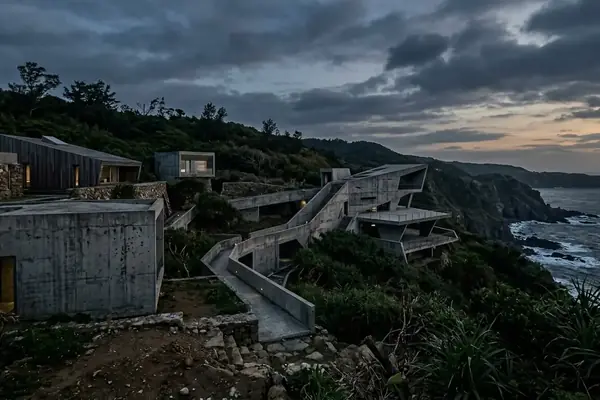
Next-Gene 20 sets up this paradox in its most demanding form. Twenty villas by the architects in the programme share ecological utilities, access roads and environmental corridors across a 65-hectare site on the Taiwanese coast. Each residence still has to read as the only building on the hill. The masterplan and vision depend on keeping those two demands in balance.
The first massing study took the easy route. It set the twenty parcels along standard contour intervals because that simplified the civil engineering. Early 3D view-shed modelling then showed upper-tier cantilevers looking straight down into the pools of the plots below. The planning consortium dropped equidistant spacing and tied each footprint to a specific micro-valley or basalt ridge. That shift made the terrain the main structural instrument of isolation, where before it had served only as scenery.
The resulting rules are strict. Setback envelopes require a minimum horizontal clearance of 45 to 70 meters between primary living pavilions, even where subterranean utility trenches run within 8 meters of a boundary line. Preliminary sightline validation took 14 to 18 weeks of iterative topographical surveying before any architectural team received locked parcel coordinates. That schedule is the cost of getting the ground right before anyone draws a wall.
Cutting Sections Every Five Meters: The 12-Degree Roof Cap
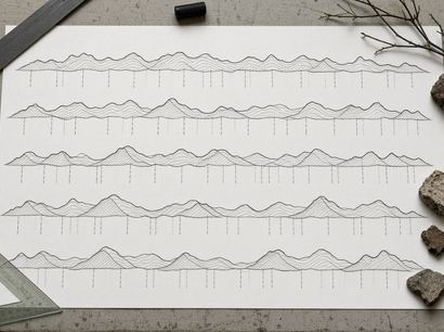
Begin with a person standing on a terrace. Their eye sits 1.65 meters above the finished slab, which is the datum the coordinators fixed for every buildable zone. From that point, a line is projected 12 degrees downward toward the Pacific. Any down-slope roof that rises through that line spoils the view.
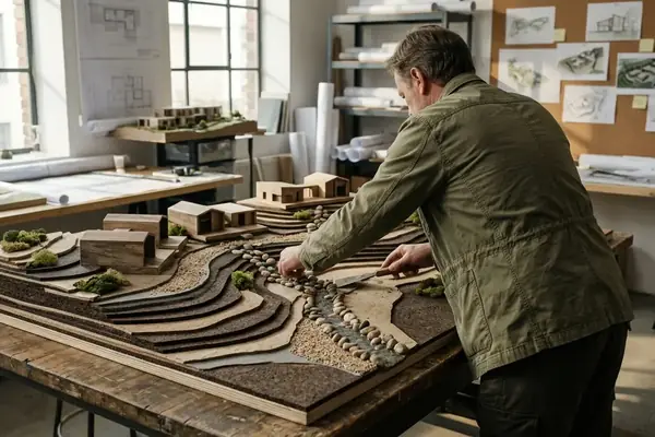
Repeat that test across section drawings cut at 5-meter intervals perpendicular to the shoreline and a pattern appears. Each parcel needs a three-dimensional frustum instead of a flat footprint. The section drawings set the building envelope, the maximum roof ridge and the terrace orientation, and the architects designed within that volume.
The consequences for the down-slope villas are physical. On gradients between 15 and 28 degrees, these houses had to recess their upper structural volumes 1.8 to 3.4 meters into the weathered sandstone substrate. Their roofs became the view for the houses above. Green roof substrates of 350 to 500 millimeters support native coastal grasses, and within 6 to 9 months of hydro-seeding the fifth facade blends into the hillside.
The margins are small. A 1.5-meter upward variance in a down-slope parapet cuts directly through the 12-degree horizon line of the terrace above, and an uninterrupted ocean view becomes a view of mechanical decking and an HVAC array. Grade changes like these also remove the need for perimeter walls, so the landscape stays continuous while neighbours drop out of view.
Parapet Tolerance Check
Treat roof parapets, rooftop plant and skylight upstands as part of the sightline envelope. A rooftop extract fan that seems minor in plan can still break the horizon line in section.
Berms, Pandanus and Rotated Glass Along the Service Corridors
The vertical geometry protects the downhill view. Shared infrastructure creates a separate problem along the horizontal plane. Graywater retention swales, electric cart tracks and utility conduits all pass between the twenty lots, and each of those routes can carry sound or open a sightline.
The landscape architecture team sized buffer thickness by recording ambient decibel levels during the seasonal northeast monsoon winds. They then placed compacted earth berms and multi-tiered windbreaks along the windward edges. The standard assembly combines 2.5-meter soil berms with dense plantings of Pandanus odorifer and Scaevola taccada, producing a visual screen 12 to 18 meters deep. That screen reduces lateral acoustic transmission by 18 to 24 decibels at 15 meters, enough to make a nearby cart track barely audible.
The buffers have a clear limit. Once a lateral terrace cantilever projects more than 3.2 meters beyond the natural ridge line, the Pandanus and Scaevola screen stops blocking oblique views across parcels. Planting cannot make up for an overreaching structure.
The architects therefore changed their villa designs. Over a design development cycle of 10 to 14 weeks, teams rotated primary curtain walls 25 to 40 degrees away from neighbouring plot boundaries. Side elevations were limited to recessed clerestories or louvered ventilation slots. Courtyards turned toward the sea, and cantilevers stayed within the envelope. The ecological integration that appears in the exhibitions and press material depends on these compromises.
Screen Depth Before Species
Set the berm height and buffer depth first, then select planting. The same native species will perform very differently on a 2.5-meter berm than on flat ground.
Seclusion Rules Worth Carrying to the Next Estate
The final permit stage made the hierarchy clear. Combining twenty separate proposals into one environmental permit package meant that any cantilever or infinity pool breaching the collective view-cone, or encroaching on a shared bioswale, had to be retracted. Sectional conflict audits across all parcels took 8 to 11 weeks of BIM coordination before primary site infrastructure broke ground.
Several rules from that process apply to other low-density ecological clusters:
- Map sectional view-cones before assigning footprints. Fix the eye-level datum and the downward sightline angle first, then let the frustum determine where architecture can go.
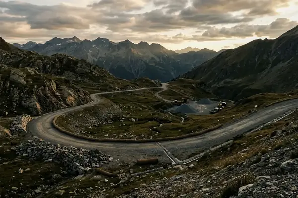
- Route shared infrastructure through troughs. At Next-Gene 20, corridors carrying medium-voltage conduits, fiber optics and storm-water cascades sit in natural troughs 6 to 10 meters wide, 2.5 to 4.0 meters below the lowest adjacent ground floor.
- Anchor parcels to landform. Micro-valleys and ridges do work that equidistant grids cannot.
- Cap lateral projection. Hold terrace cantilevers within the distance at which the planted buffer still screens oblique views.
These rules depend on slope. Vertical view-cone masking requires a natural gradient of at least 12 degrees. On flatter coastal plains, recessing a down-slope house far enough to clear the upslope horizon reaches the water table and reduces cross-ventilation. On such sites, I would put more effort into horizontal buffers and depend less on section.
The trade-off remains on every site. Each extra degree of panorama given to one villa reduces the acoustic and visual isolation available to the rest of the estate. Developers tend to favour the hero view, while the masterplan has to protect the whole collective.
What the Section Decides
View allocation is a matter of land use. Settle it in section, before the plan is fixed.
When your next multi-residence masterplan forces a choice between an unobstructed horizon view and an uncompromised shared ecological corridor, which one will your section drawings sacrifice first?